Choosing a structural framing system is an engineering decision. What that decision does to the BIM model and the drawing set that comes out of it is a drafting question — and it’s a different answer for wood, light-gauge steel, and hybrid construction, even on buildings with similar footprints.
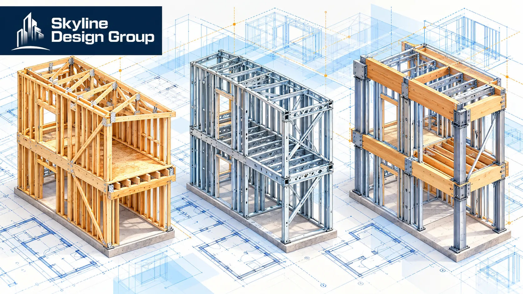
Wood, light-gauge steel, and hybrid framing systems demand different things from a structural BIM model: wood plans emphasize member sizing and panelization; light-gauge steel models carry detailed assembly data tied to manufacturer component families; hybrid systems need the transition point between the two systems coordinated precisely, since that’s where most clashes and RFIs originate.
Who this is for
This is for structural engineers and architects deciding between framing systems, or already committed to one, who want to know what actually changes in the model and drawing set — not just the engineering, but what the detailer has to track differently.
Why hybrid systems exist in the first place
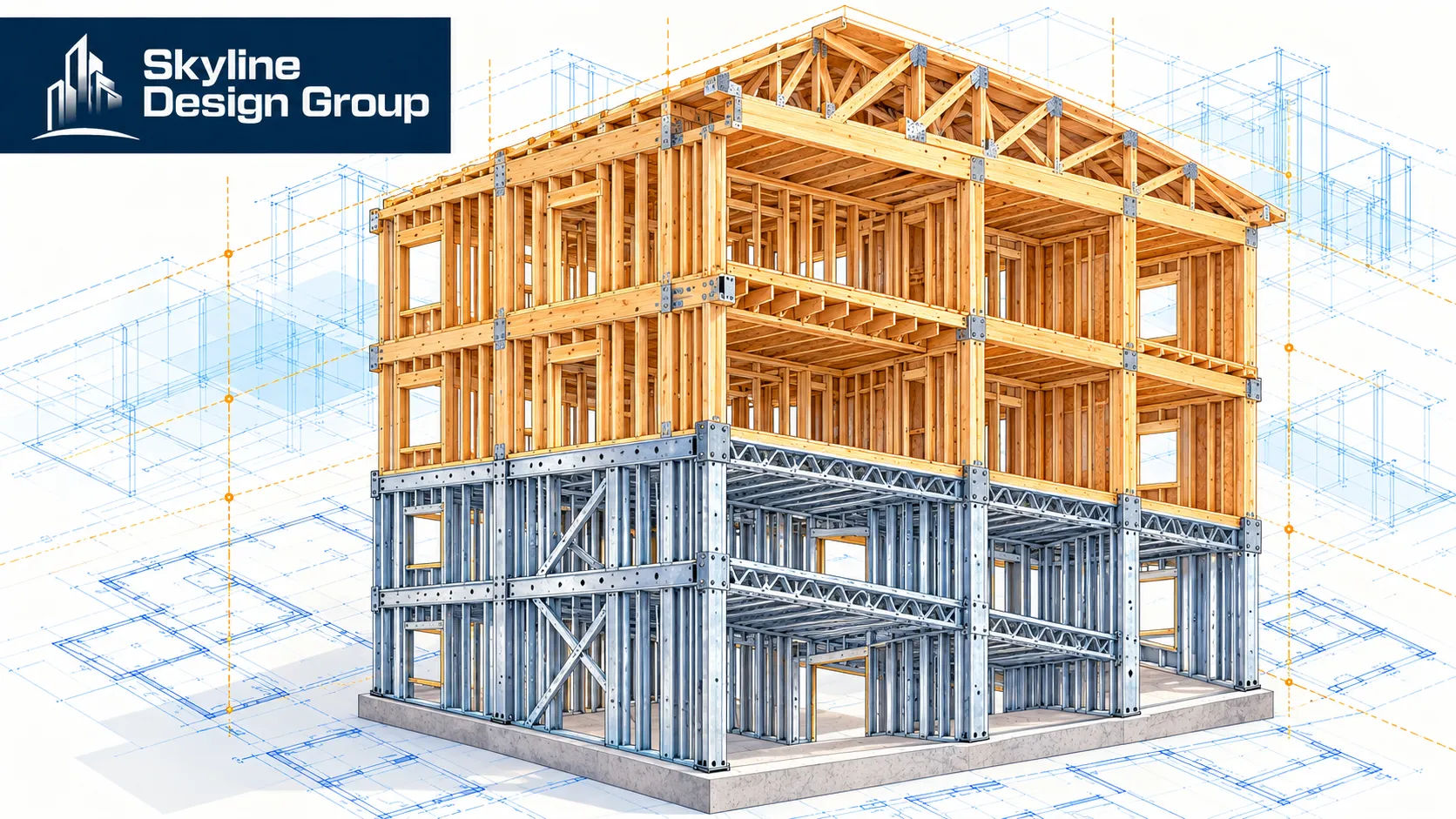
A STRUCTURE magazine article on structural system selection lays out the cost hierarchy plainly: “wood construction is generally considered the most cost-efficient form of construction, followed by cold-formed steel (CFS) bearing walls and then heavy steel or concrete framing.” Wood is cheapest and fastest, but it hits height and fire-rating limits. That’s where hybrid construction comes in — the article describes stacking CFS bearing walls beneath wood-framed upper levels as an alternative to a full steel or concrete podium, letting a project get taller than wood alone allows without the full cost of a steel or concrete base [CLIENT TO CONFIRM — cost hierarchy is general industry guidance; project-specific costs vary by market and should be confirmed with the engineer of record].
The same source flags what actually has to get coordinated at that transition: fire-rating assemblies (the article cites a 3-hour requirement under IBC Section 510.2 for certain configurations), mechanical routing through wall cavities, and lateral bracing compatibility between the two systems. None of that is a drafting decision — it’s engineering — but every one of those items has to show up correctly in the model, because the transition level is where clashes and RFIs concentrate.
What changes in the model itself
Wood framing plans are mostly about member sizing, spacing, and panelization notes — the model and drawing set track dimensional lumber or engineered wood members, their spans, and nailing/fastening schedules. Light-gauge (cold-formed) steel framing carries a different kind of information load. A manufacturer’s BIM documentation for cold-formed steel systems describes models built around detailed assembly data — fire ratings, sound (STC) ratings, and design properties — tied to specific component families, with tools built specifically to generate “detailed family assemblies” of products and run clash checks against them [CLIENT TO CONFIRM — specific tools and workflow are manufacturer-specific; confirm which component library and Revit families, if any, the project’s engineer or detailer standardizes on].
| Framing type | What the model emphasizes | Where RFIs tend to originate |
|---|---|---|
| Wood | Member sizing, spacing, panelization, fastening schedules | Shear wall nailing patterns, blocking at penetrations |
| Light-gauge (cold-formed) steel | Assembly data (fire/sound ratings), manufacturer component families, clash checks | Track/stud gauge mismatches, missing bridging, connector conflicts |
| Hybrid (CFS base + wood above) | Transition-level coordination between the two systems | Load path continuity, fire-rating assembly at the transition, MEP routing through the transition level |
Where detailing support fits

Skyline builds the framing model and drawing set to the structural engineer’s design and member schedules — modeling wood, light-gauge steel, or hybrid assemblies to the dimensions, connections, and assembly types specified, and running coordination/clash checks against the rest of the model. Skyline does not select the structural system, size members, or determine fire-rating assemblies; those stay with the structural engineer of record [CLIENT TO CONFIRM — confirm this boundary matches current service scope]. This is the same scope boundary covered in 6 rebar detailing errors that turn into field RFIs for reinforced concrete — the detailer models to spec and flags visible inconsistencies; the engineer owns the design decisions.
What a framing-plan reviewer actually checks, system by system
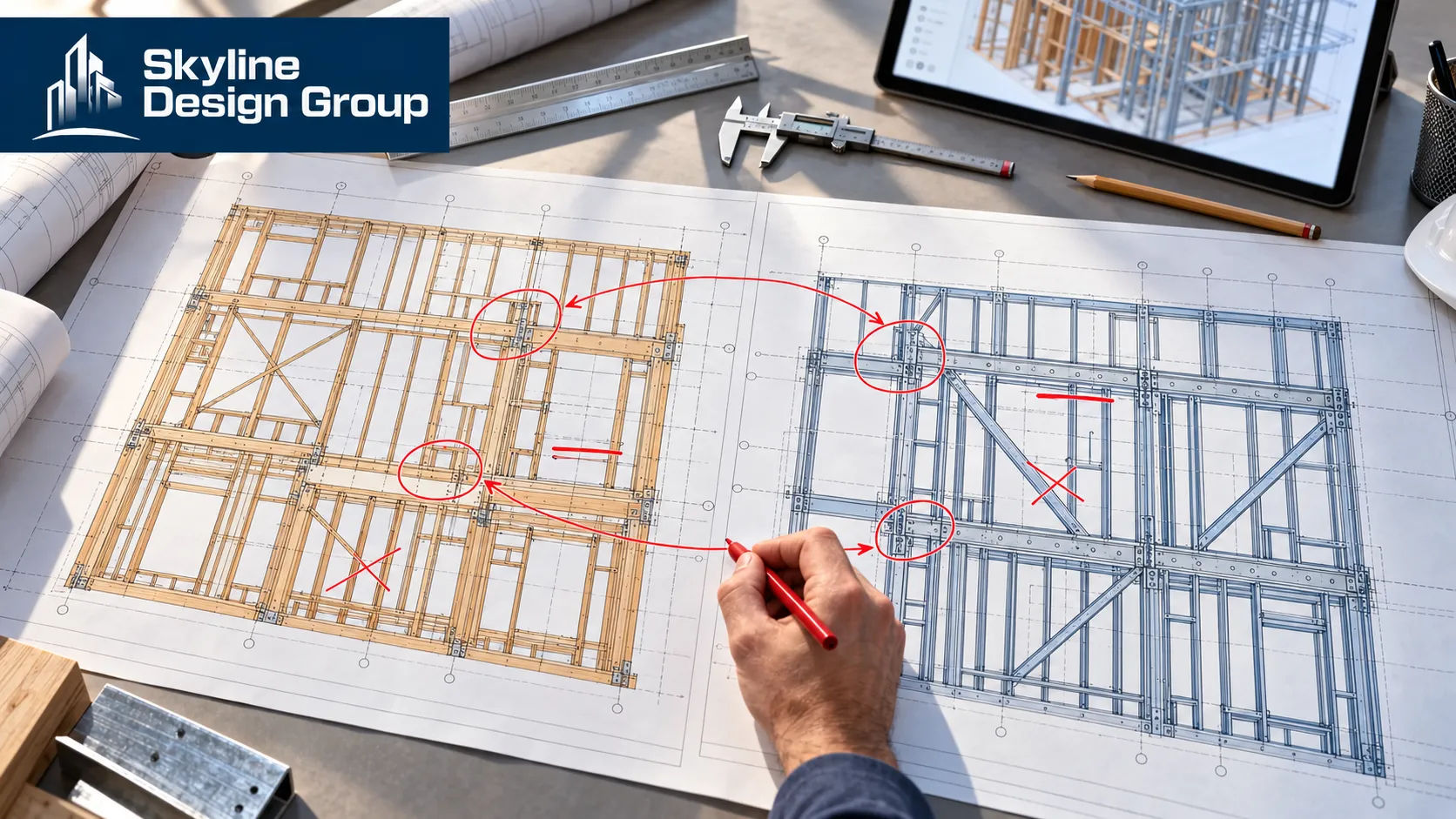
A framing plan gets checked differently depending on the system, because the information that matters differs. On a wood framing plan, a reviewer is mostly confirming member sizes against span tables, checking that shear wall and diaphragm nailing schedules are called out correctly, and verifying blocking is shown at penetrations and bearing points. On a light-gauge steel framing plan, the check shifts toward whether the stud and track gauges called out match the engineer’s design, whether bridging and bracing are shown at the intervals specified, and whether the connector types at each condition match what the manufacturer’s load tables actually support for that gauge and spacing.
On a hybrid system, both of those checks still apply to their respective portions of the building — but the transition level gets a third, more involved review: does the load path stay continuous from the wood framing above into the CFS bearing walls below, does the fire-rated assembly at that level match what the code requires for the configuration, and do mechanical, electrical, and plumbing runs that cross the transition have a clear path without conflicting with either system’s framing. That third check is where a hybrid project’s RFI count tends to concentrate if the transition wasn’t modeled carefully the first time.
If you’re modeling a hybrid framing system and want the transition level checked for coordination before it goes to the field, Request a Scope Review — send the current framing model and schedules and get back a specific read on what’s coordinated and what needs another pass.