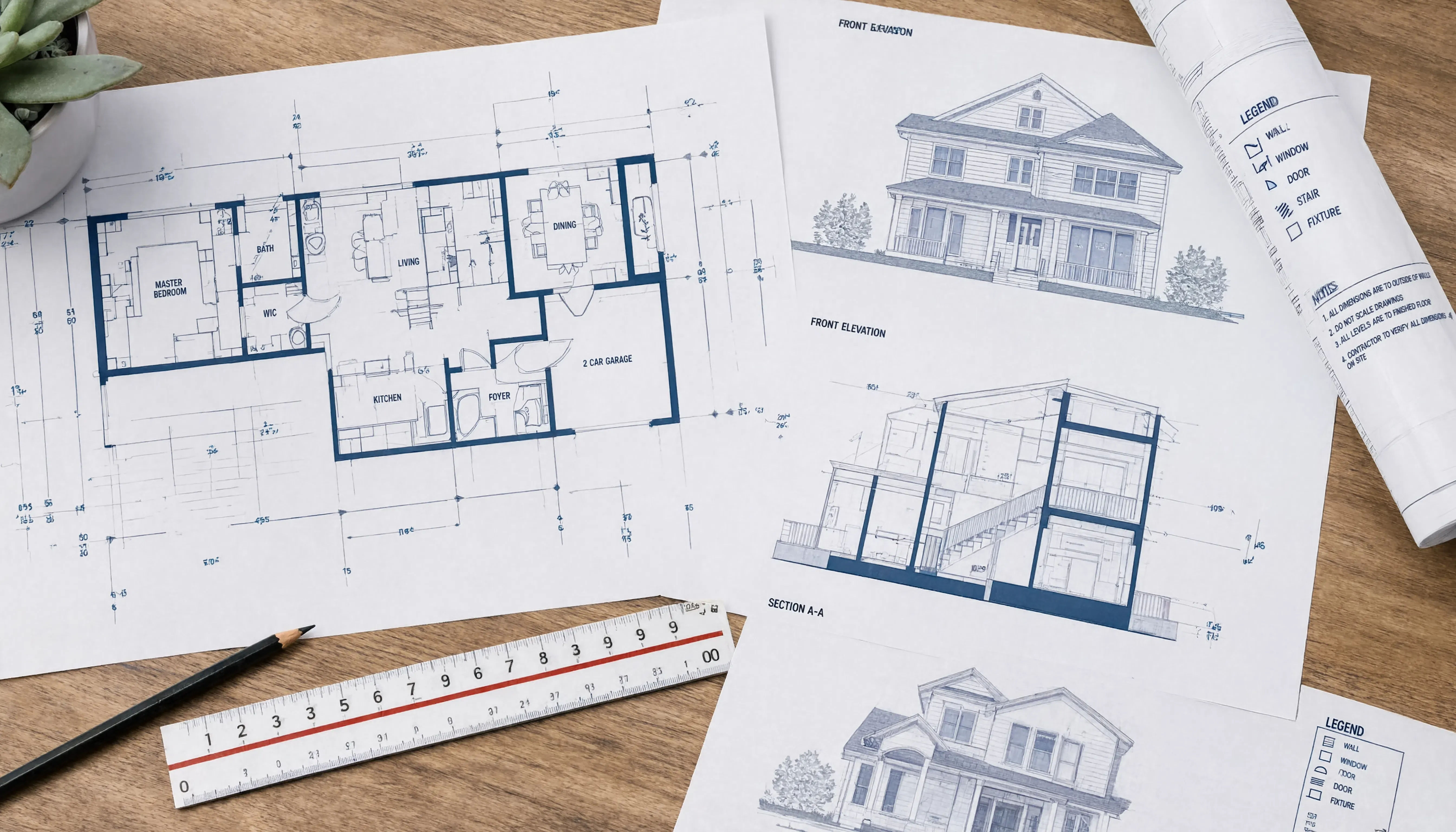
What Are Architectural Drawings? The 7 Types Every Homeowner and Developer Needs to Know
Ask a contractor what they need to build and they’ll tell you: drawings. Ask what kind and the answer gets complicated fast. Floor plans, elevations, sections, details — each one is a different view of the same project and each one serves a different purpose.
Knowing the difference matters more than most clients realize. It affects what you pay for, what you can use for permits and what information your contractor actually has when they show up on site.
Here’s a plain-English breakdown of the seven types of architectural drawings you’re most likely to encounter — what they show, why they exist and when you need them.
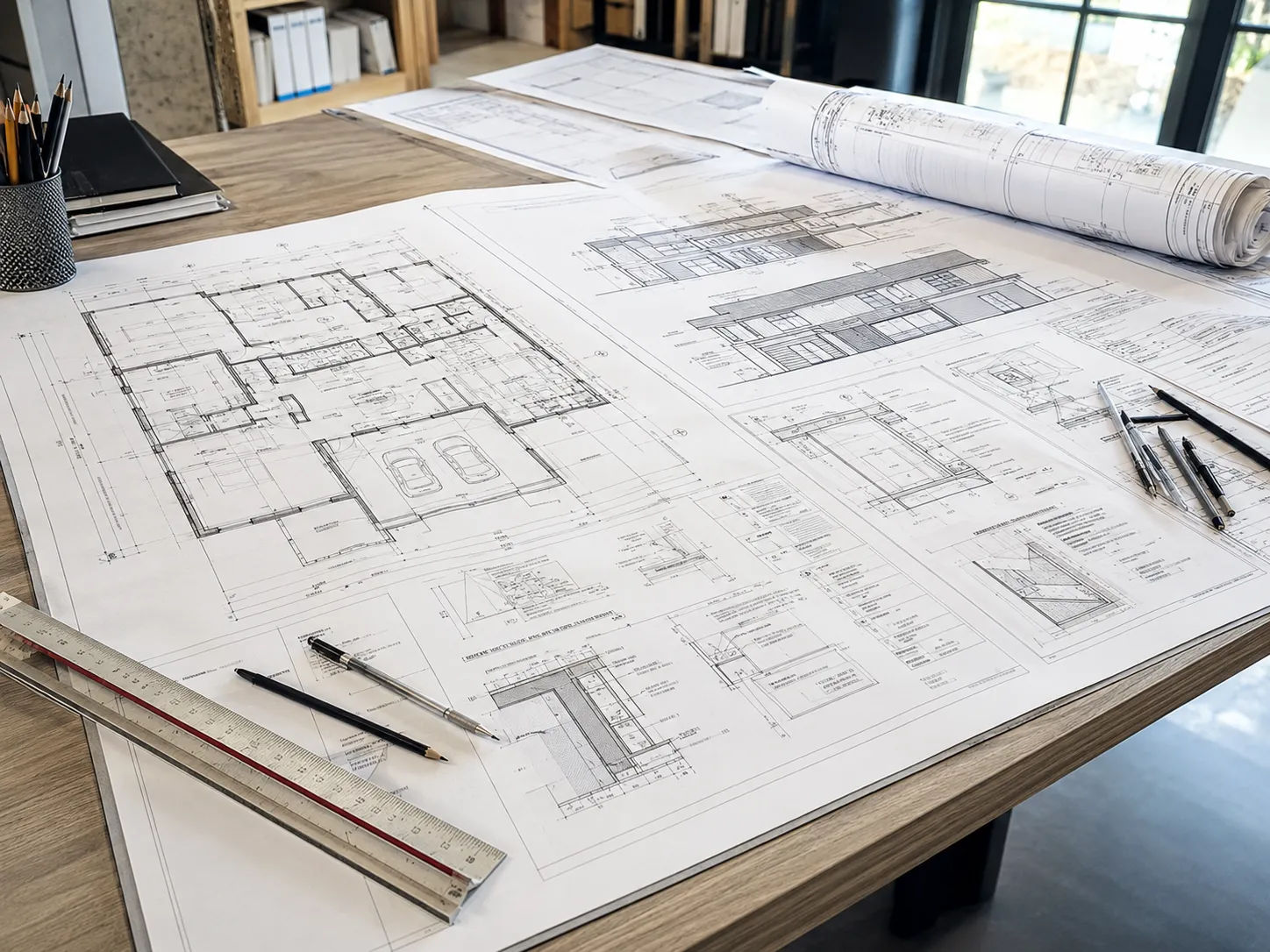
1. Site Plans
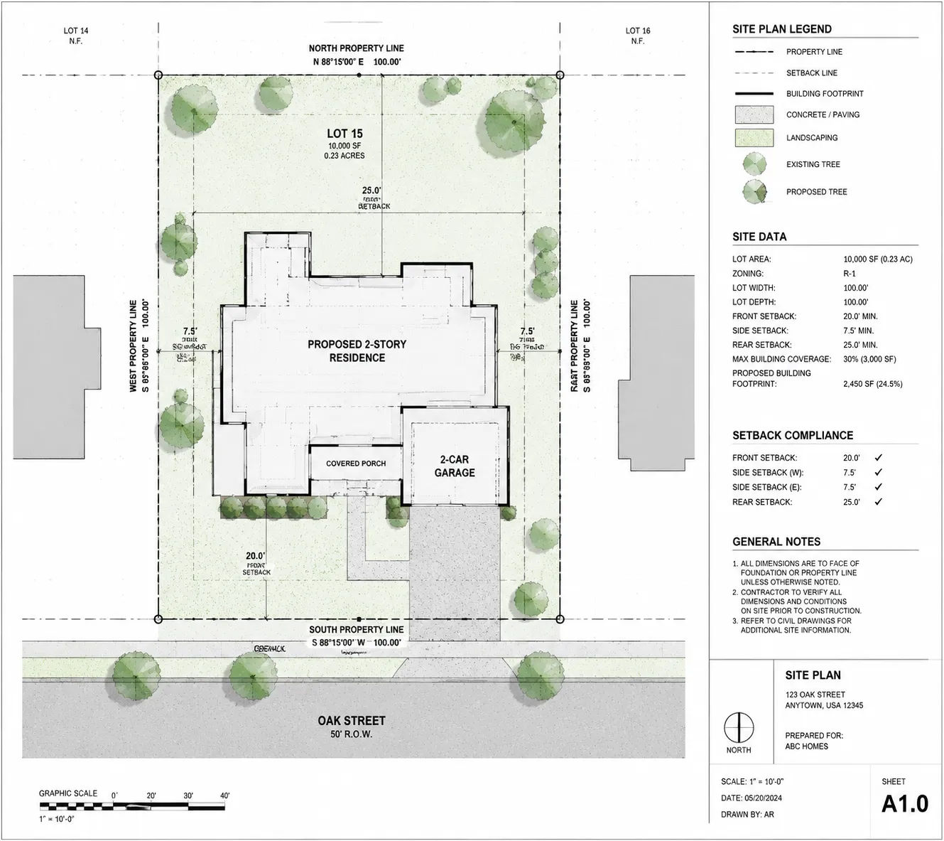
The site plan shows the property from above — the bird’s-eye view. It includes the building footprint, property lines, setbacks, access points, parking, landscaping and utilities.
This is almost always the first sheet in a permit submission package. The municipality needs to see how the building sits on the lot and that it complies with zoning requirements — setbacks, lot coverage, easements.
You won’t build from a site plan. But you can’t get a permit without one.
2. Floor Plans
Floor plans are probably what most people picture when they think “architectural drawings.” They’re horizontal cuts through the building — as if you sliced off the roof and looked straight down.
A floor plan shows: - Room layout and dimensions - Wall locations (including which are structural) - Door and window locations - Stairs, elevations and level changes - Fixed furniture and equipment (in some versions)
Every level of a building gets its own floor plan. A two-story house has a ground floor plan and an upper floor plan. A three-unit building has three.
Floor plans are used by clients to understand the space, by contractors to frame and build and by permit offices to evaluate layout compliance with code (egress requirements, occupancy loads, accessible routes).
3. Elevations
An elevation is the flat, straight-on view of a building’s exterior — like a photograph taken from directly in front, with no perspective distortion.
There are typically four exterior elevations: north, south, east and west. Each shows: - The exterior facade treatment and materials - Window and door locations and sizes - Building height and roofline - Grade level relative to the building
Elevations are what municipalities use to evaluate aesthetic and contextual requirements — particularly in historic districts or design-reviewed neighborhoods. They’re also what contractors reference when building facades and installing exterior windows and cladding.
For interior work — kitchen renovations, custom cabinetry, accent walls — you’ll also encounter interior elevations, which apply the same flat-view logic to interior surfaces.
4. Sections
A section is what you’d see if you cut straight through a building vertically and looked at the cut face.
It shows how floors stack, how roof structure works, how the building’s height relates to interior ceiling heights and how stairs connect levels. It’s the drawing type that makes three-dimensional drafting relationships legible on a 2D sheet.
Sections are critical for: - Understanding multi-story drafting relationships - Structural coordination (where beams sit, how foundations connect to walls) - Showing energy compliance (insulation thickness, thermal assemblies)
If a floor plan is a horizontal cut, a section is a vertical one. Together, they give a complete picture of how the building is organized.
5. Construction Details
Details are enlarged drawings of specific parts of the building — typically shown at a scale large enough to convey precise dimensions and material relationships.
Examples of what details cover: - How a window is installed in a wall assembly - How a roof edge flashes and drains - How two materials meet at a corner - How a stair tread is constructed
Details exist because floor plans and elevations can’t show everything at the scale they’re drawn at. A floor plan might show that there’s a wall, but it can’t show — at that scale — how the wall is insulated, how the vapor barrier is detailed or how it connects to the floor system. Details fill that gap.
Contractors reference details constantly during construction. Missing or unclear details are a leading cause of field RFIs (requests for information) — which slow the job down and cost money.
6. Reflected Ceiling Plans
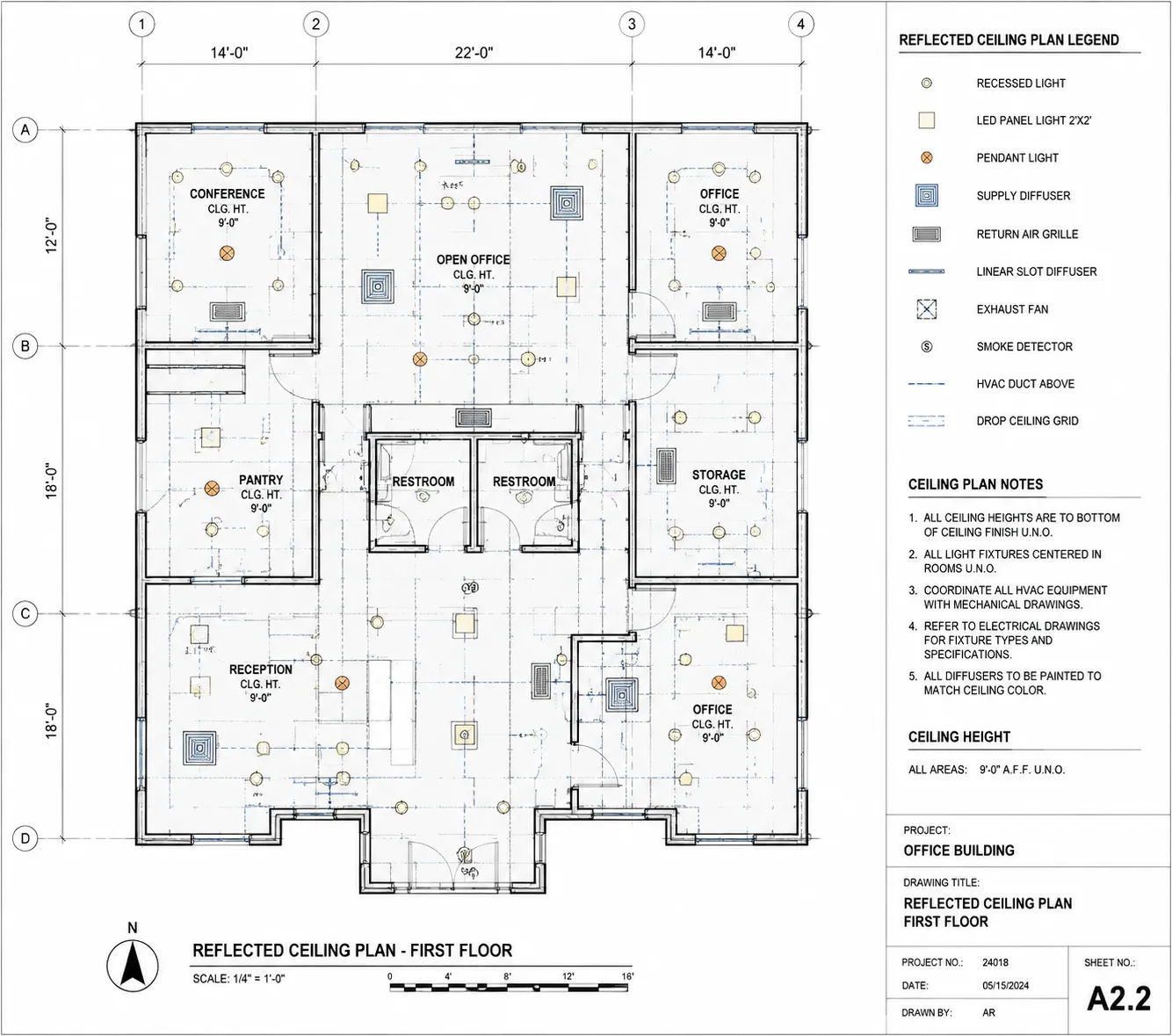
A reflected ceiling plan (RCP) shows the ceiling as if you were looking up at it — or, as the name suggests, as if the ceiling was reflected in a mirror on the floor.
It shows: - Ceiling heights and changes in height - Light fixture locations and types - Mechanical diffusers (HVAC supply/return) - Sprinkler heads - Soffits and dropped ceilings
RCPs are essential for coordination. Electrical, mechanical and architectural teams all need to know what’s happening at the ceiling plane — and it’s a common collision zone where systems conflict. Getting this drawn and coordinated before construction prevents expensive ceiling conflicts on site.
7. 3D Drawings and Visualizations
3D drawings aren’t traditionally listed as a “type” of architectural drawing — but they’ve become standard enough to include here. These range from simple wireframe 3D models to photorealistic renderings to fully interactive walkthroughs.
They don’t replace construction documents. A 3D visualization can’t be submitted for a permit. But they serve critical purposes:
- Client understanding: Clients understand 3D images far better than flat plans
- Investor and lender communication: Financing often requires visual representations
- Design coordination: 3D models (especially BIM models) allow clash detection before construction
Pre-construction visualization has grown significantly as a service because its value is clear: seeing the project before building it catches problems that drawings sometimes miss.
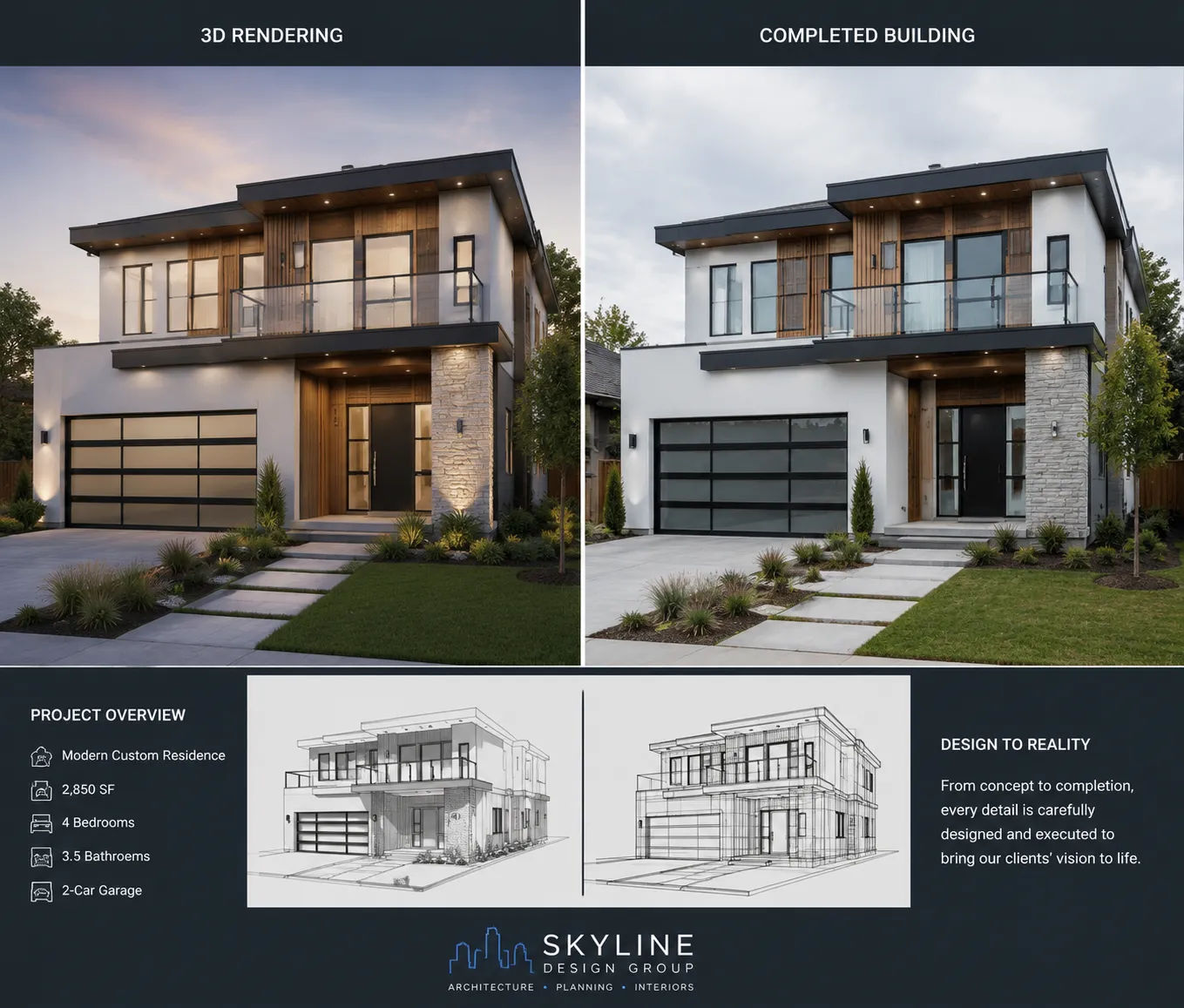
How These Drawing Types Come Together in a Real Project
A standard permit package for a new residential building typically includes: a site plan, foundation plan, floor plans for each level, four exterior elevations, at least two building sections, key construction details and a reflected ceiling plan. That’s the minimum a permit office will usually accept.
For construction, contractors need everything above plus additional detail sheets specific to the trades — structural framing plans, MEP coordination drawings, finish schedules.
Knowing which types you need for your project — and at what stage — helps you scope the work correctly. Planning drawings explained goes deeper on what’s required at each stage of a project.

