By the time precast panels are on a truck headed to the site, it’s too late to discover the erection drawings are missing a connection detail or a bracing sequence. Erection drawing content isn’t a judgment call — most precast specifications spell out exactly what has to be on the sheet, and checking against that list before delivery is cheaper than finding the gap in the field.
Precast erection drawings need to show unit layout and dimensions, piece identification marks, connection details with hardware locations, lifting/handling device locations, erection sequence, and a bracing/temporary support plan. Specifications commonly require erection drawings to be sealed by a professional engineer and reviewed before fabrication — not assembled after the fact.
Who this is for
This is for GC project executives coordinating a precast delivery and erection schedule who need to know exactly what should be on the drawings in hand before panels show up — not a general description of precast, but the specific content list a spec actually requires.
What the drawing has to show
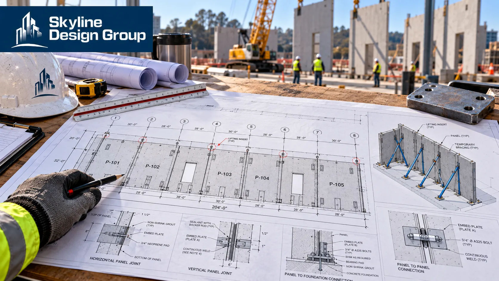
A structural precast concrete specification lists required erection drawing content in detail: “layout plans with unit locations, bearing and top of unit elevations, overall dimensions, building cross sections, wall sections, details, and opening locations,” plus individual elevation and dimensioning for each unit type with identification marks. Beyond the layout, the same spec requires welded connection details using AWS standard symbols (size, length, type), hardware and anchorage device locations, lifting and handling device locations, reinforcing steel quantities and positions, shim sizes and grouting sequence, and — critically for scheduling — “handling procedures, sequence of erection, and bracing plan” [CLIENT TO CONFIRM — this is one manufacturer’s specification section; confirm the exact content list against the project’s own governing specification].
A separate federal facility specification covering precast erection drawings lists a similar but not identical set: plans and elevations locating material furnished by the manufacturer, sections and details showing connections and cast-in items relative to the structure, a description of loose/cast-in/field hardware, field-installed anchor location drawings, erection sequences and handling requirements, and the design loads (dead, live, and other applicable loads) used in the design [CLIENT TO CONFIRM — spec requirements vary by project and governing agency; confirm against the specific contract documents].
Who prepares and seals the drawing
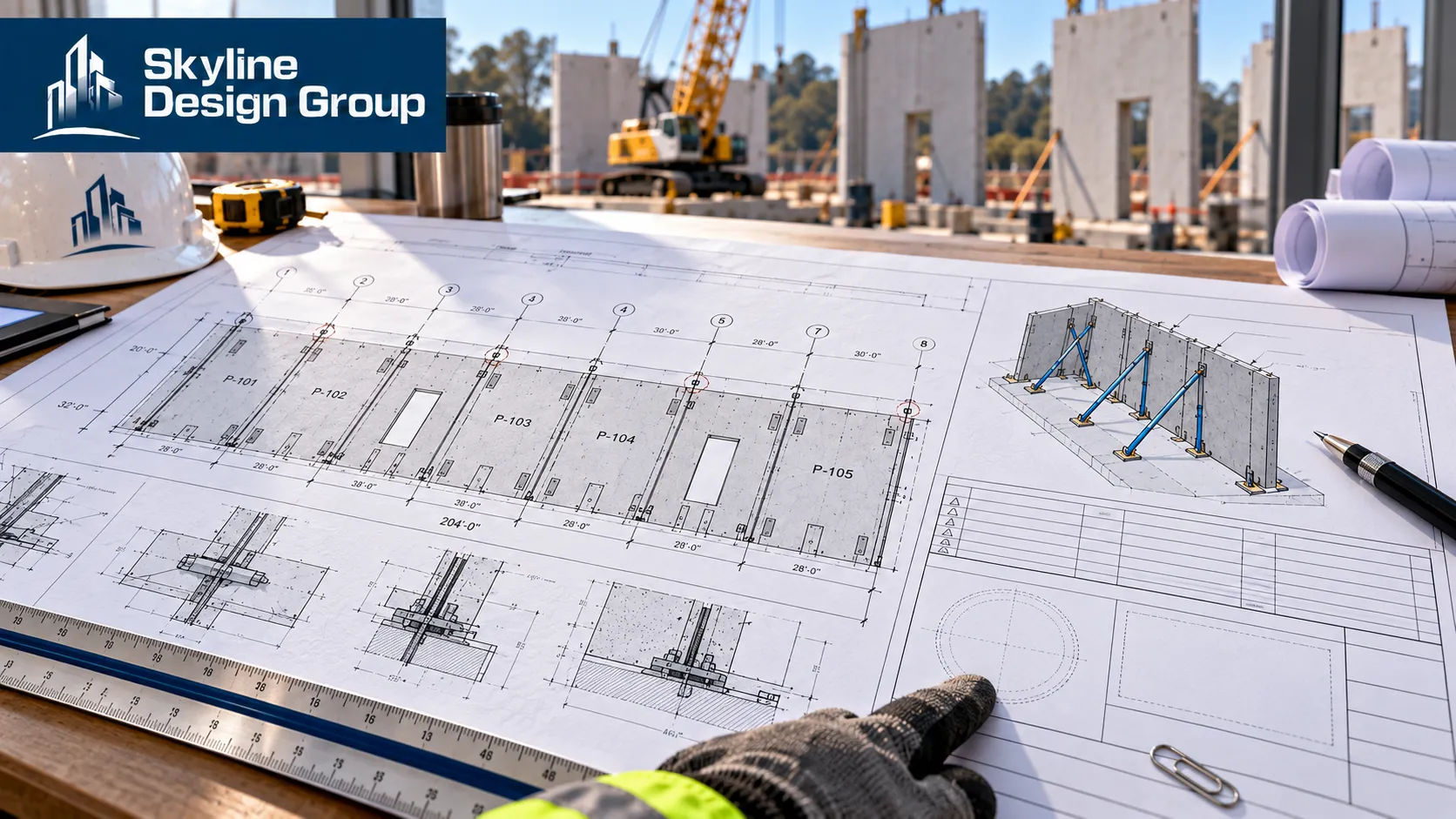
One of these specifications is explicit that erection drawings must be “prepared and sealed by a Professional Structural Engineer,” submitted for review and approval before work proceeds — not an informal field document assembled after the fact. That review-and-approval step is built into the submittal process, not an optional add-on [CLIENT TO CONFIRM — seal/sealing requirements vary by jurisdiction and specification; confirm the specific requirement for the governing contract].
| Erection drawing content | Why a GC checks for it before delivery |
|---|---|
| Unit layout, dimensions, elevations | Confirms panels will actually fit the sequence and location planned |
| Piece identification marks | Lets field crews match delivered panels to the correct erection position |
| Connection details (welded/bolted/cast-in) | Confirms the field crew has what it needs to make each connection correctly |
| Lifting/handling device locations | Determines crane rigging points and lift plan |
| Erection sequence and bracing plan | Determines the order panels go up and what temporary support is needed before the next panel loads against it |
| Engineer seal/review sign-off | Confirms the drawing has gone through the required design review before fabrication |
Why this matters for scheduling, not just compliance
A missing bracing plan or an unclear erection sequence doesn’t just create a paperwork gap — it stalls the crew on site, because panels can’t safely go up without knowing what temporary support is required between pieces. Checking the erection drawing against a known content list before delivery is scheduled is a lower-cost way to catch that gap than discovering it once the crane is mobilized.
This connects to the same coordination concerns covered in steel connection detail packages and where delegated design starts — connection detail completeness is a recurring theme across structural trades, not unique to precast.
What to check against the drawing before delivery is scheduled
A practical pre-delivery check doesn’t need to re-verify the engineering — it needs to confirm the drawing actually contains what the spec requires before the panels leave the plant. Pull the governing specification section, lay the content requirements next to the erection drawing set, and confirm each item is present: layout and unit dimensions, piece marks matching the delivery manifest, connection and hardware details for every condition shown on the layout, lift points, erection sequence, and the bracing plan. If the specification requires an engineer’s seal, confirm it’s present before the drawing is treated as final.
This is a formatting and completeness check, not a design review — it’s meant to catch an omission on the drawing itself (a connection detail that was never added, a bracing note that got dropped in revision) before that omission becomes a stalled crew on site. A design review of whether the erection sequence or bracing plan is actually adequate, structurally sound, and sufficient for site conditions stays with the engineer of record, not with whoever is running this completeness check.
If you need erection drawings checked against your project’s specification before precast delivery is scheduled, Request a Scope Review — send the current drawings and spec section and get back a specific read on what’s complete and what’s missing.