
Monument Building and
Section Views for Sidewalk
Monument building and section views for a sidewalk are detailed construction drawings that show the design, size, shape, and placement of a monument structure near or along a sidewalk. These plans help explain how the monument will look from the outside and how it will be built internally.
The section views show a cut-through view of the sidewalk and monument area, including layers such as concrete, base material, soil, curb, foundation, reinforcement, and drainage slope. These drawings are important because they guide construction workers, help prevent building mistakes, and make sure the sidewalk and monument are safe, stable, accessible, and built according to project requirements.
This project drawing presents an overall site plan and multiple cross-section sheets. Together, the drawings communicate the proposed site layout, grading conditions, utilities, parking areas, landscape elements, and sectional elevation changes across the project. The sheets are organized in a professional engineering format with title blocks, general notes areas, revision tables, north arrow, and graphic scales.
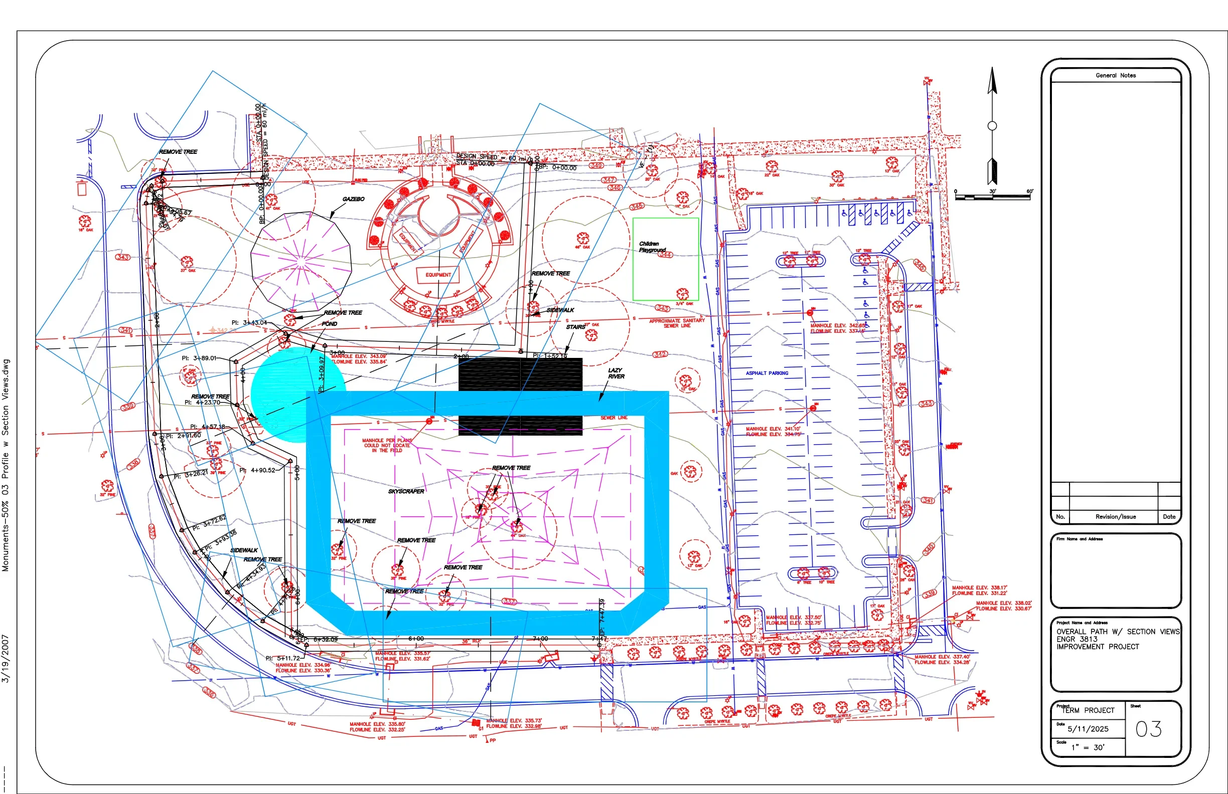
Overall Site Plan
The main plan sheet shows the complete project area with existing and proposed site features. It includes building footprints, circulation paths, parking layout, sidewalks, utility lines, manholes, sanitary sewer information, trees, and landscape features. The drawing uses different line colors to distinguish between existing conditions, proposed improvements, utility networks, grading information, and site design elements.
Project Location and Layout
The plan identifies the main improvement area and shows how different site elements connect together. A large central structure or feature is highlighted, with surrounding pedestrian paths, landscape areas, driveways, and parking spaces. The plan also shows adjacent property edges, road connections, and site circulation routes.
Parking and Circulation
A large asphalt parking area is shown on the right side of the site plan. It includes parking stall striping, drive aisles, curb lines, and access points. This portion of the drawing communicates vehicle movement, parking organization, and the relationship between the parking lot and the rest of the site.
Pedestrian and Public Areas
The plan includes sidewalks, walkway connections, a gazebo area, a children’s playground, seating or equipment zones, and landscape areas. These elements show how pedestrians move through the site and how outdoor public-use spaces are arranged.
Landscape and Tree Information
Trees and landscape features are shown throughout the plan, including several notes for tree removal. Tree symbols and circular canopy limits help identify existing vegetation, proposed landscape impact areas, and coordination needs during construction.
Utilities and Drainage Information
The site plan includes utility-related notes such as sanitary sewer lines, manhole elevations, gas lines, and other underground service references. These annotations help coordinate grading, site improvements, and utility connections during design and construction.
Grading and Elevation Data
The drawing includes contour lines, spot elevations, and manhole rim/invert elevations. These details help explain existing and proposed ground conditions and support the design of drainage, pavement slopes, and utility flow.
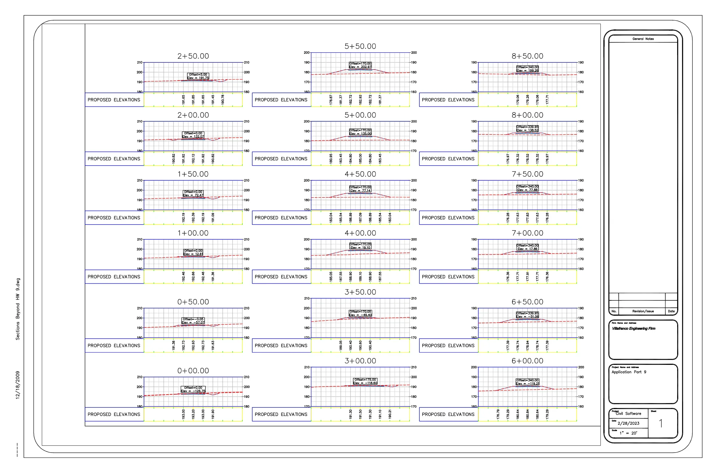
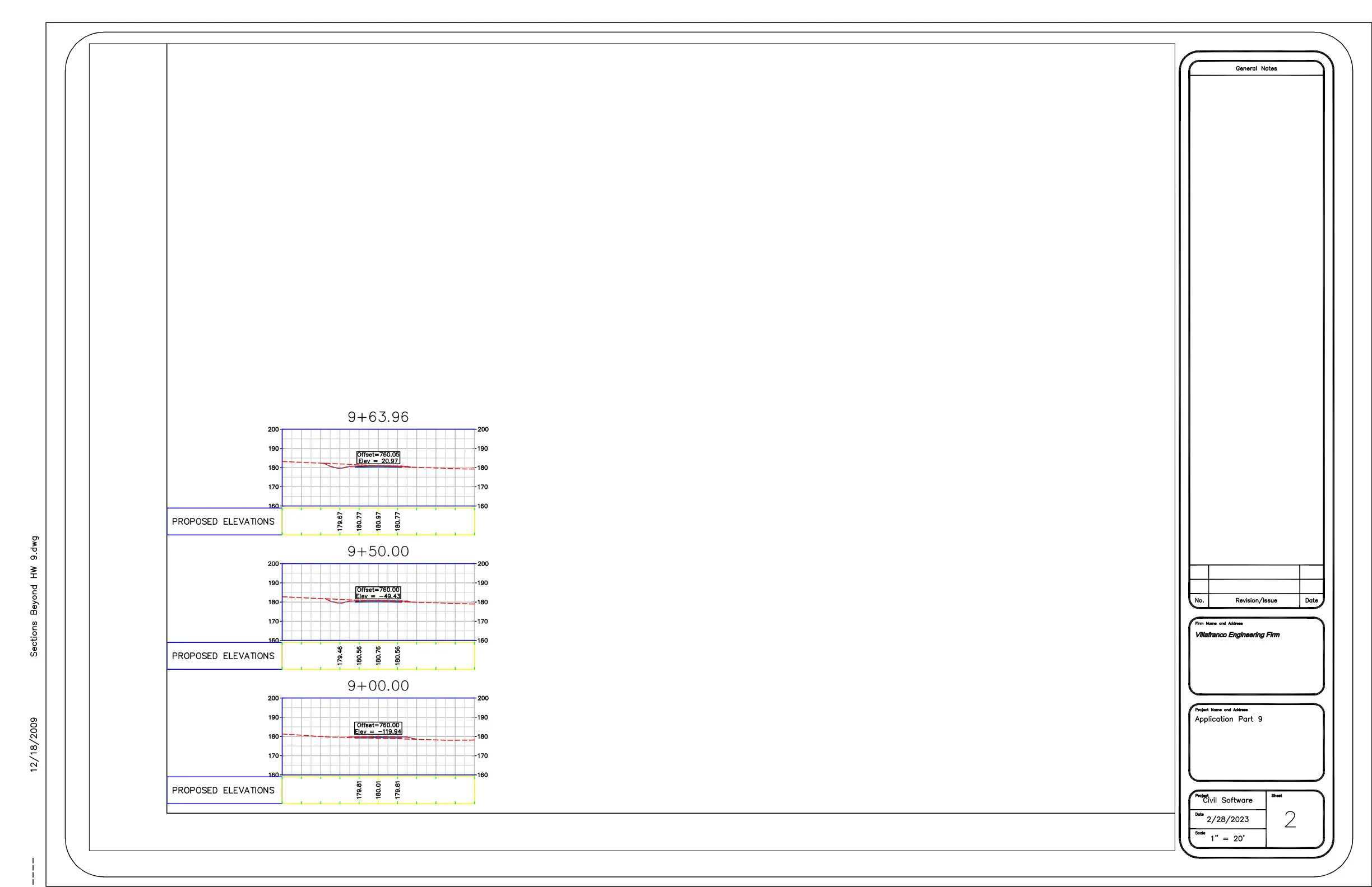
Cross-Section Sheets
The second and third sheets present multiple cross-section views at different station locations, including stations such as 0+00, 0+50, 1+00, 1+50, 2+00, 2+50, 3+00, 3+50, 4+00, 4+50, 5+00, 5+50, 6+00, 6+50, 7+00, 7+50, 8+00, 8+50, 9+00, 9+50, and 9+63.96. Each section shows the relationship between existing ground and proposed elevations.
Proposed Elevation Profiles
Each section includes a grid with elevation values and a labeled area for proposed elevations. The dashed profile lines and plotted section lines show how the ground surface changes across the improvement area at each station. These views are useful for reviewing grading design, earthwork requirements, and proposed site elevation transitions.
Station-Based Site Analysis
The cross sections are organized by station number, allowing the design to be reviewed at regular intervals across the project. This makes it easier to understand how the proposed improvements respond to the existing terrain and how elevations change from one part of the site to another.
Engineering Documentation
Each sheet includes a title block with project information, date, scale, sheet number, firm information, and revision area. These elements support formal civil design documentation, permitting, construction review, and project coordination.
Overall Purpose
Overall, this drawing set demonstrates a coordinated civil improvement design with detailed site planning and grading analysis. The overall plan explains the physical layout of the project, while the section sheets provide elevation-based information needed to evaluate grading, drainage, utilities, and construction feasibility.